I
guess every
electronics geek made their fair share of astable multivibrators with
555 ICs, and I'm no exception. When I saw advertisement for this 555 design contest,
I did
not pay too much attention at first. But then I got an idea: "hey, its
name is 555
design contest,
not
555-with-other-components-contest. Could I actually construct something
using 555s as the only
components in the entire design?" The result has been a resounding "yes"!
And so, I'm presenting you one of my contributions to the contest - a
classical astable
multivibrator
that is
made solely from 555 ICs. No resistors, no capacitors or other
components... well, at least not in their common form. And the same
concept can be applied to many, many other 555-based circuits. I've
chosen the astable multivibrator as the example, because everybody
knows how it works.
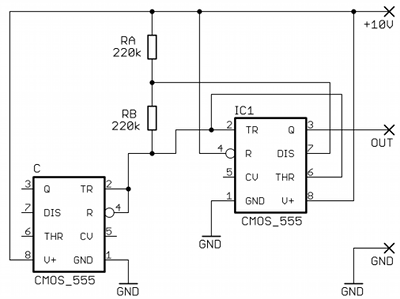
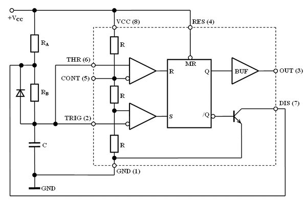
2 Multivibrator schematic
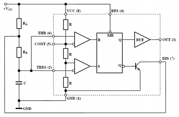
Just for the sake of completeness, let's have a quick look at the
classical 555 astable
multivibrator schematic in figure 2.1.
Figure 2.1. Astable
multivibrator with 555
Okay, so the question was, how
can I leave out RA,
RB and C from that schematic?
Well, I did not
leave them
out, I just used other 555s to make them. Both resistors and capacitors
can be actually found inside the 555 IC structure. I tried this with
both bipolar and CMOS versions of the 555 IC and I suceeded both times.
Resistor replacement was pretty easy fo figure out. It is a
well-known fact that every single 555
contains a voltage divider
made of three resistors which is connected between pins 1 and 8. In the
bipolar version, its overall resistance is 15 kΩ. But the capacitors
were a big question. So for my experiments, I bought four 555
types from two different producers, 11 pieces of each type. All were in
DIP
packages, because breadboarding is so much easier with them compared to
SMD components. In case somebody wants to repeat my experiments
exactly, actual part numbers and Farnell order codes of parts
I used are in table 2.1.
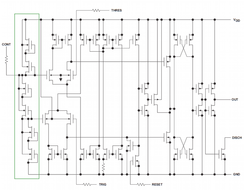
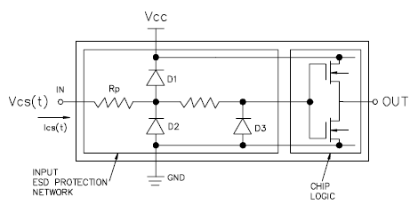
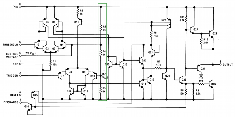
In figure 3.1 you will find internal schematics of CMOS 555 which I
ripped from Texas Instruments' datasheet. Here, the main
voltage divider is formed by a cascade of self-biased transistors
(green rectangle in figure 3.1). Its
resistance is 240 kΩ in case of TLC555CP
and 220 kΩ
in case of LMC555CN. I measured 10 pieces of each type
and differences between individual pieces were
around ±2 kΩ.
Figure 3.1. Internal schematic
of CMOS 555
But where to find a capacitor inside the 555? Well, this is
why I first turned my
attention to the CMOS version of the chip - theoretically, the silicon
oxide layer between transistor gates and
channels should behave as a quite good capacitor. Normally, this
capacitance is considered a parasitic
property, but is sometimes employed in useful on-chip
capacitors. I have this handy
RLC meter Escort
ELC-131D,
which can measure capacitance and loss tangent at the
same time thanks to its dual display. So I measured every combination
of CMOS 555 pins to see which ones have as large capacitance as
possible, but at the same time, as low loss tangent as possible. My
prime candidates were pins 2, 4 and 6, because they are inputs with
just one transistor gate connected to them. Measurements
confirmed this assumption - combinations of pins 1-2, 1-4 and 1-6 had
the best results. I thought this was because pin 1 is
connected
with semiconductor substrate (bulk) of the chip. In case of LMC555CN,
the capacitances were around 50 pF with tangent loss of
0.7. TLC555CP was even better, the capacitances
were 75
pF while the tangent loss remained around 7. I was a bit surprised that
I measured such high capacitances (CMOS gate capacitances are usually
in the order of femtofarads), but I was thrilled that my 555-only
contraption might actually work, so I did not pay much attention.
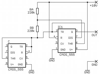
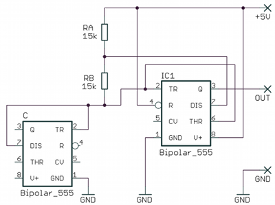
And so I built multivibrator according to figure 3.2a on a solderless
breadboard - I used normal resistors as RA
and RB, but I
connected another CMOS 555 instead of C. And... it failed to oscillate.
It worked fine with a normal capacitor, but with "capacitor 555", it
did nothing. I tried everything I could think of - I varied supply
voltage, I tried many different values of RA
and RB, I tested
every combination of "capacitor 555" pins I could devise - but the
circuit always failed to oscillate.
a)
b)
Figure 3.2. Schematic of wrong
connection of CMOS "capacitor 555" (a) and working circuit (b)
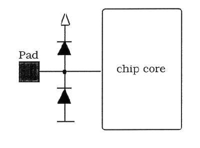
I was about to give up when I realized one very important detail:
today, every input pin of CMOS integrated circuits is
protected
against ESD!
This protection usually has the form of fast diodes which are
connected in reverse polarity between the input pin, GND and power
rail. You can see two examples in figure 3.3. I found the simpler
circuit in figure 3.3a here
and I copied the more complex circuit in figure 3.3b from this
application note. The RLC meter takes only small-signal
measurement of the capacitance,
meaning that test voltage is well under 1 V. Moreover, there is no DC
voltage present on the capacitor during the measurement (only expensive
benchtop RLC meters can do that). Such small voltage of course couldn't
engage the ESD protection diodes, so such measurements looked fine. But
in 555 astable multivibrator, the voltage on the capacitor moves
between 1/3 and 2/3 VCC, which is in the order of volts - which is high
enough for the protection diodes to become
conductive. So I
had to make sure that the diodes would not engage - and they could
engage only if there was voltage higher than VCC or lower than GND on
any input pin. But with pin 8 floating like in figure 3.2a, the high
voltage limit was not defined. In other words, I had to connect the
power pin (8) of the
"capacitor 555" to supply voltage, so the protection diodes would be
always reverse polarized, as is illustrated in figure 3.2b. And then the circuit began to oscillate!
Afterwards, I also realized why my RLC meter showed capacitances of
dozens pF on every 555 input - what it actually measured were
the barrier
capacitances
of those protection diodes. Of course, the transistor gates and wires
on the chip have their capacitances too, but my guess is that they're
tiny compared to diodes' capacitances. After some experiments, I found
out
that only pin combinations 1-2 and 1-4 can be realiably used as
"capacitor 555". Pins 2 and 4 also could be connected together to make
one bigger capacitance. Pin combination 1-6 worked too, but was
unreliable - sometimes the circuit failed to start oscillating after
powerup or there were false pulses in the output signal. My best guess
is that the "capacitor 555" did not like the fast signal changes on all
its inputs (2, 4, 6) at once and its internal structure behaved
erratically. So if you want to try this, I recommend schematic
according to figure 3.2b.
a)
b)
Figure 3.3. Two examples of CMOS input
pin protection circuits
After that, only one step remained - to replace normal
resistors RA
and RB
with 555s. This went without problems and the circuit
oscillated like with normal resistors... almost.
There was one difference which will be explained in chapter
3.2. Note that the "resistor
555s" have to be connected so that pin 8 has positive potential in
relation to pin 1.
I
also found out that the circuit was somewhat unstable with +5 V power
supply - large jitter (sometimes as large as 20% of the entire period)
could be sometimes seen on the output signal. But this disappeared when
I raised the supply voltage to +10 V.
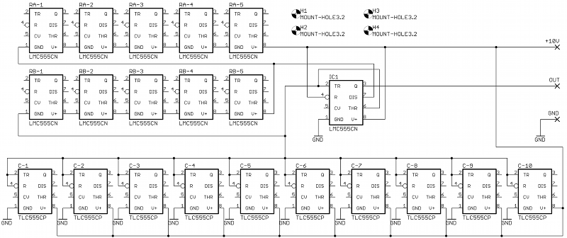
3.1 CMOS test board
Well, the experiments on the solderless breadboard turned out pretty
good, the circuit really worked in the end. But
I was met with scepticism when I've shown the working circuit to my
friends. I heard "nah, you have those passive components hidden inside
the beadboard" or "that breadboard has so big parasitic capacitances
that the
capacitances inside 555s are negligible" etc. And so I decided to make
a simple "test board" to prove them wrong. To make it more versatile, I
designed it so up to five 555s can serve as RA,
five 555s can serve as RB
and ten 555s can be placed as C. Schematic of the board is in figure
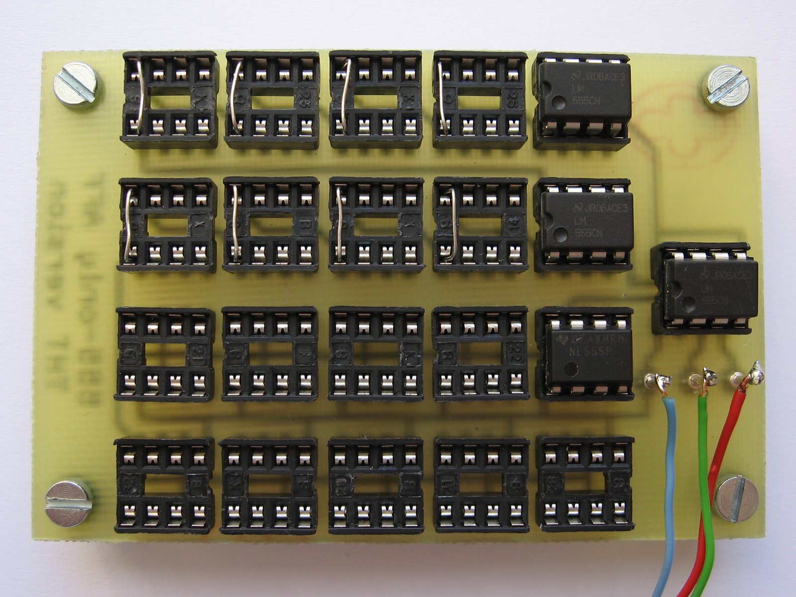
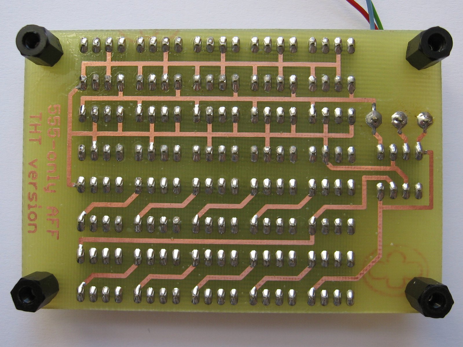
3.4, its layout is in figure 3.5; its dimensions are 83x60 mm.
As
you can see, the only components on the board are 555s... 21 of them,
to be precise.
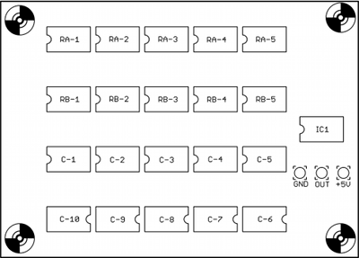
Figure 3.4. Schematic of CMOS
multivibrator test board
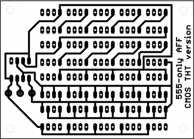
Figure 3.5. Layout of CMOS
multivibrator test
board
I created the board in freeware version of Cadsoft Eagle 5.11,
you can
download the source files here.
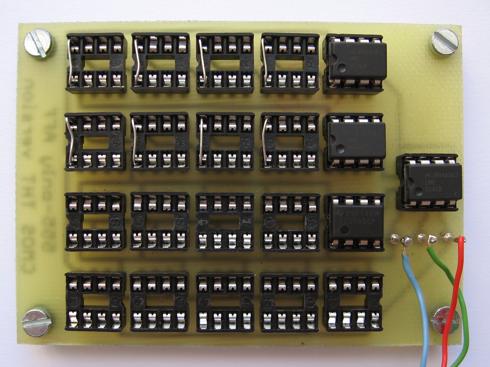
The board was produced by wet rapid prototyping (photomask and iron
chloride etching) and drilled by hand. I soldered socket for
every
555, so I could add or remove the ICs easily during my experiments.
Since the "resistor 555s" are connected in series, a wire must be
placed into their socket if not populated by actual 555 IC.
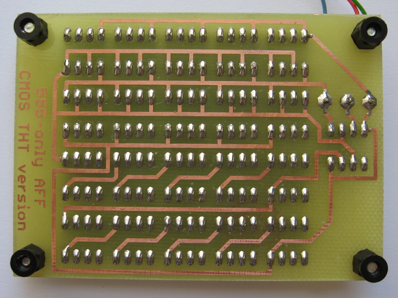
Figure 3.6. Photographs of CMOS test
board (click for larger images)
3.2 Measurement results
Measurements were taken with the help of Agilent DSO6032A digital
oscilloscope and were done on the test board. Note that part numbers in
figure 4.3 exactly match with reality - I used LMC555CN
as resistors, TLC555CP as capacitors and LMC555CN as
the actual
multivibrator IC (I tried other combinatons of part numbers as well,
but I got similar results). Using the
oscilloscope, I measured times of "high" and "low" states on the
multivibrator output (IC1 pin 3) and also the overall frequency. These
results are in table 3.1. Measurements were done with +10 V supply
voltage.
Table 3.1. CMOS multivibrator frequency for
different number of "passive component 555s"
555s
serving as RA
555s
serving as RB
555s
serving as C
thigh
[μs]
tlow [μs]
freq
[kHz]
1
1
1
11.4
0.15
87.0
1
1
2
12.4
0.15
80.6
1
1
3
13.8
0.15
72.5
1
1
4
15.2
0.15
65.8
1
1
5
16.8
0.15
59.3
1
1
6
18.3
0.15
54.5
1
1
7
19.8
0.15
50.4
1
1
8
21.3
0.15
46.9
1
1
9
22.7
0.15
44.0
1
1
10
24.2
0.15
41.2
2
1
10
43.0
0.30
23.3
2
2
10
54.8
0.60
18.3
3
2
10
69.8
0.60
14.3
3
3
10
82.4
0.60
12.1
4
3
10
104
1.50
9.62
4
4
10
108
1.50
9.30
5
4
10
128
1.50
7.84
5
5
10
127
1.50
7.91
Here is video where I demonstrate that the multivibrator really
works. Note that measured frequencies in the video are a little
different from those in table 3.1; this is because I made those
measurements in different days.
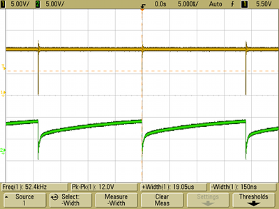
Oscilloscope screenshot of multivibrator waveforms is in figure 3.7.
Yellow
trace is output signal (IC1 pin 3) and green trace is voltage on
the "capacitor 555s". The figure shows these
signals with one 555 as RA, one 555 as RB
and one 555 as C (configuration according to the first row
in table 3.1). Note that measured frequency in table 3.1 is
different from the frequency in figure 3.7; this large difference was
caused by parasitic capacitance of the oscilloscope probe (Agilent
10073C) when I connected it to the "capacitor 555". Therefore,
all
measurements in table 3.1 were taken without the probe on the capacitor.
Figure 3.7. Output and
capacitor waveforms of multivibrator with with 1 RA, 1 RB and 1 C
As you can see from the results, the thigh time
and frequency nicely scales with the number of "capacitor 555s." On the
contrary, the tlow time is always very short
(the output signal has over 99% duty cycle) and stays short even when
more RB
"resistor 555s" are added. This happens due to presence of the internal
ESD protection diodes. When "capacitor 555" discharges during tlow
time, reverse current flows through RB
and voltage on it also reverses. But since RB
is actually another 555, its ESD diodes open... and of course, an open
diode has much lower resistance than 220 kΩ. I
was even able
to measure diode's drop voltage with a diode tester (it was around 0.6
V as expected). So in reality, the
multivibrator behaves more like equivalent circuit in figure 3.8.
Figure 3.8.
Equivalent circuit representing actual behavior of the
multivibrator
4 Bipolar version
After the success with CMOS version, I turned my attention to bipolar
555s. Figure 4.1 shows their internal schematics as can be found in
National Semiconductor's
datasheet. Again, the main voltage divider is easy to see. Now the
question was if there were some components that could be used as
capacitors.
Figure 4.1. Internal schematic
of bipolar 555
Bipolar version has no ESD protection diodes, so their barrier
capacitance could not be used. Therefore, I tried to find some other
reverse-polarized PN junctions, so I could employ them as the capacitor
C. When pin 1 is connected to ground, base-collector junctions of
transistors Q7 and Q14 are reverse polarized, which meant that pins 2
and 7 could be used for that purpose. So I made test
circuit according to figure 4.2a on breadboard and amazingly, the circuit oscillated!
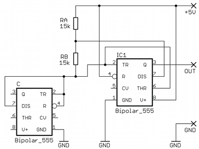
Resistors RA
and RB have value
of 15 kΩ in this circuit, because I planned to replace them with
another bipolar 555s. After a few experiments, I found out that pin 4
can also be used as a capacitor - while it wasn't immediately apparent
from the internal schematic, its base-collector junction is too reverse
polarized. So if you want to try this, you can use schematic in figure
4.2b, it has the highest capacitance I could find inside
bipolar 555.
a)
b)
Figure 4.2. First
testing schematic (a) and final version (b) of bipolar "capacitor 555"
Unfortunately, even the combined capacitance of all three pins is very
small, it was under 10 pF in all 555s I measured. This, coupled with
much lower RA
and RB values
(compared to CMOS), resulted in high output frequencies in the range of
hundreds of kHz. Unlike the CMOS version, the bipolar
multivibrator worked reliably at
+5 V supply voltage and was still operating even when I decreased it to
about 3.5 V.
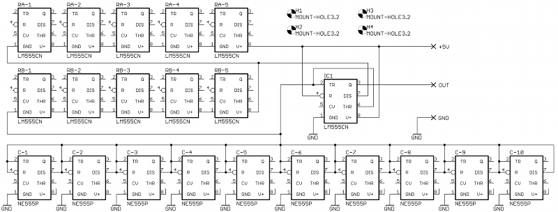
4.1 Bipolar test board
The bipolar test board is very similar to the CMOS one, practically the
only difference is in connection of "capacitor 555s". The board is
slightly smaller (83x56 mm) than its CMOS counterpart, because there
are
less copper traces on it.
Figure 4.3. Schematic of
bipolar test board
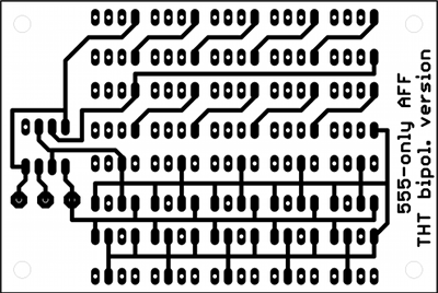
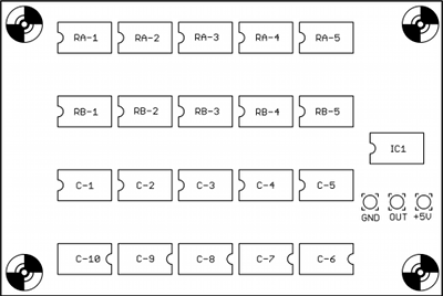
Figure 4.4. Layout of bipolar test
board
You can
download Eagle source files of this board here.
Some people asked me why there are short pieces of wire
(Nets) connected to pin 8 of every "capacitor 555". Well, Eagle has
this "smart" function that it automatically connects all power pins
which have the same name. To prevent this behavior, I had to connect
every pin 8 to a different signal, which was easiest done by drawing a
short net to it.
Figure 4.5. Photographs of bipolar
test board (click for bigger images)
4.2 Measurement results
I
made the same measurements as with the CMOS version, the only
difference was that I used +5 V supply voltage this time. Measured
results are in table 4.1. As you can see, the internal capacitance
of bipolar 555s is really low - every added "capacitor 555"
caused only slight
decrease of the output freqency. Adding "resistor 555s" had more
significant impact, but compared to the CMOS version, the output
frequencies were still 5 to 10 times higher.
Table 4.1. Bipolar multivibrator frequency for
different number of "passive component 555s"
555s
serving
as RA
555s
serving
as RB
555s
serving
as C
thigh
[μs]
tlow [μs]
freq
[kHz]
1
1
1
0.98
0.13
905
1
1
2
1.05
0.13
855
1
1
3
1.10
0.11
826
1
1
4
1.17
0.12
775
1
1
5
1.23
0.12
740
1
1
6
1.31
0.12
699
1
1
7
1.38
0.13
667
1
1
8
1.44
0.13
639
1
1
9
1.49
0.12
623
1
1
10
1.56
0.11
601
2
1
10
4.53
0.11
216
2
2
10
7.12
0.8
126
3
2
10
9.85
0.8
93.9
3
3
10
11.6
2.0
73.5
4
3
10
13.8
2.0
63.3
4
4
10
16.1
5.0
47.4
5
4
10
18.7
5.0
42.2
5
5
10
20.8
7.6
35.2
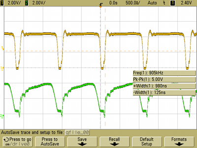
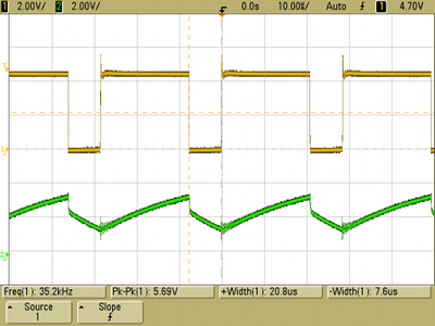
Oscilloscope screenshots of output waveforms are in figure 4.6.
Again, yellow traces are output signals and green traces are voltage on
the "capacitor 555s". Figure 4.6a shows output
signals with one 555 as RA, one 555 as RB
and one 555 as C. Figure 4.6b shows output signals with five 555s in
series as RA, five 555s in series as RB
and ten parallel 555s as C (in other words, all sockets on the test
board were populated). This represents the first and the last row
in table 4.1, respectively. Measurements of the bipolar version were
too affected by oscilloscope probe parasitics, but their influence was
not as grave as in the CMOS version.
a)
b)
Figure 4.6. Output waveforms with 1 RA,
1 RB, 1 C (a) and with 5 RA, 5 RB,
10 C (b)
Times tlow are again very short so the
bipolar version behaves more like circuit in figure 3.8, too.
But every added RB prolongs it aproximately by
1.5 μs, so the
output signal duty cycle moves between 70 and 90% (the CMOS
version always had over 99%).
Conclusion
Well, the good news is that both versions of the multivibrators really
work! However, I guess their usefulness is limited - especially the
CMOS version produces signal with duty
cycle over 99% and the circuit is somewhat sensitive to touch or other
movements of foreign objects in its proximitiy. The CMOS version is
capable of producing low freqencies around 8 kHz - quite a surprise,
considering that one "capacitor 555" value is on the order of
pF.
The bipolar version can produce only much higher frequencies,
but its output waveforms look somewhat better.
Now I have to devise a meaningful use for those 44 pieces of
555 ICs I bought for the experiments...